Hydraulic Diverter Valve Schematic is probably the most viral images on the web at this time. In addition to those photos, Common Symbols Used in Pneumatic Systems and Instrumentations, Directional Control Valves Classification by Port/Position Count and Hydraulic Control Valve Symbols additionally skilled a big increase in search trends. If you are in search of trending photographs related to Hydraulic Diverter Valve Schematic, on this web page we’ve got 35 photographs for you to explore. Right here you go:
Hydraulic Diverter Valve Schematic

userdataaccretions.z14.web.core.windows.net
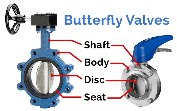
What Is A Butterfly Valve? | How Does A Butterfly Valve Work?
www.plumbersstock.com
butterfly valve valves diagram does work types
[DIAGRAM] 3 Way Solenoid Valve Diagram – MYDIAGRAM.ONLINE
![[DIAGRAM] 3 Way Solenoid Valve Diagram - MYDIAGRAM.ONLINE](https://www.researchgate.net/profile/Rudi_Kobetic/publication/3415342/figure/download/fig3/AS:394693935419404@1471113775981/Schematic-of-the-Allenair-two-way-two-position-solenoid-valves-The-NC-valves-can-be.png)
mydiagram.online
How To Apply Safety Edge (Pressure Sensitive) Devices – Part 2

machinerysafety101.com
valve schematic pneumatic symbols read block spring solenoid symbol apply edge safety blocked part oid solen down welcome
[DIAGRAM] 3 Position Valve Diagram – MYDIAGRAM.ONLINE
![[DIAGRAM] 3 Position Valve Diagram - MYDIAGRAM.ONLINE](https://control.com/uploads/textbooks/valve_56.jpg)
mydiagram.online
Directional Control Valve Symbol

ar.inspiredpencil.com
[DIAGRAM] Mack Valve Diagram – MYDIAGRAM.ONLINE
![[DIAGRAM] Mack Valve Diagram - MYDIAGRAM.ONLINE](https://techblog.ctgclean.com/wp-content/uploads/Rotary-Valve1.jpg)
mydiagram.online
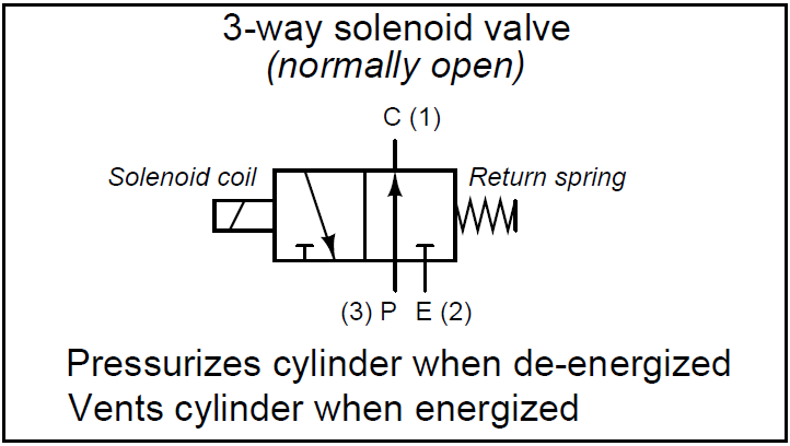
Three Way Valve Diagram – Wiring Diagram And Schematics
www.caretxdigital.com
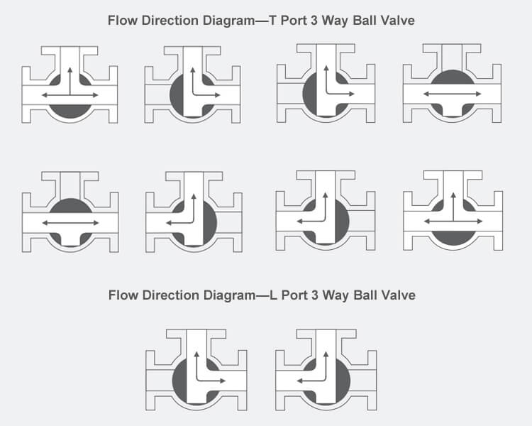
3 Way 2 Position Valve Schematic
manualenginemcadams.z5.web.core.windows.net
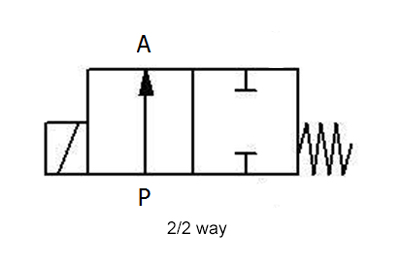
5 Way 2 Position Valve Schematic
schematicpartclaudia.z19.web.core.windows.net
3 Way Pneumatic Valve Schematic Diagram – Wiring Diagram

www.organised-sound.com
Hydraulic Schematic Diagram Symbols
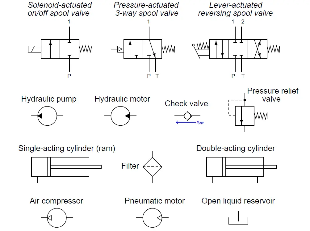
mungfali.com
Flow Control Valve Schematic

mavink.com
Basic Hydraulic Schematic Diagram

guidemanuallubricated.z21.web.core.windows.net
Hydraulic And Pneumatic P&ID Diagrams And Schematics – Inst Tools
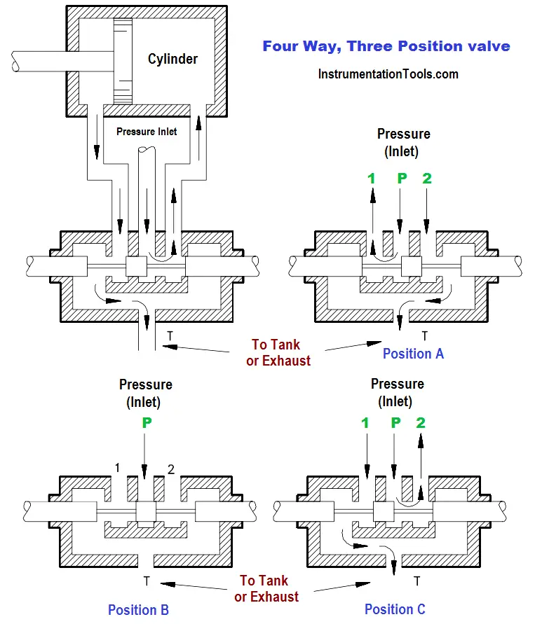
instrumentationtools.com
valve hydraulic pneumatic diagrams schematics way operation pid four figure
Hydraulic Control Valve Symbols
puntodeenvio.es
valve symbols hydraulic control pneumatic valves port types hydraulics system introduction vent atmosphere systems figure 6d shown various
Common Symbols Used In Pneumatic Systems And Instrumentations
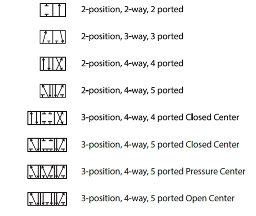
www.instrumentationtoolbox.com
symbols pneumatic control directional valves used engineering common instrumentation
Drayton 3 Port Mid Position Valve Wiring Diagram – Wiring Diagram

www.diagramelectric.co
What Is Directional Control Valve (DCV)? – Inst Tools
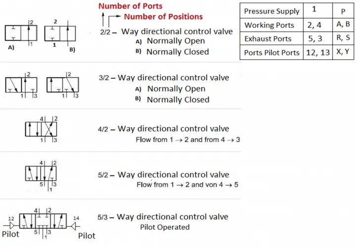
instrumentationtools.com
Diagram Of Valves

manualdatasiphonogam.z21.web.core.windows.net
Machine Drawing: Rotary Four Way Valves
machine-drawing.blogspot.com
control direction way valves four hydraulics methods drawing actuation part
Hydraulic Valve Port Letters At Jesse Novack Blog

gioitdwil.blob.core.windows.net
Directional Control Valves Classification By Port/Position Count

www.hydraulicstatic.com
directional control valves hydraulic port position symbols classification ports schematic troubleshooting graphic
Motor Operated Valve Schematic Diagram

manualdiagramchristin.z13.web.core.windows.net
Wiring Diagram For Solenoid Valve – Wiring Diagram

wiringdiagram.2bitboer.com
Triple Duty Valve Schematic Symbol

manuallibraryengravre.z21.web.core.windows.net
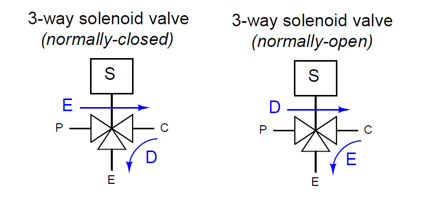
What Is A 3-way Solenoid Valve ? | Instrumentation Tools
instrumentationtools.com
valve solenoid way three schematic asco instrumentationtools actual photographs manufactured appear here
3 Way Pneumatic Valve Schematic Diagram – Wiring Diagram
www.organised-sound.com
What Is Meant By A 4/3 Dc Valve At Charles Barker Blog

gioloznpm.blob.core.windows.net
4 Way 2 Position Valve Schematic

schematicpartclaudia.z19.web.core.windows.net
3 way pneumatic valve schematic diagram. Three way valve diagram. 4 way 2 position valve schematic
