Schematic diagram of full-depth artificial freezing technology in is one of the viral photos on the internet right now. In addition to those photographs, Schematic representation of disintegrators DSA-2 (a), DSL-115 (b) and, Disintegrator system DSL-175; a) Disintegrator system DSL-175 in a lab and Schematic diagram of depth image refinement method | Download additionally experienced a major enhance in search trends. In case you are in search of viral images related to Schematic diagram of full-depth artificial freezing technology in, on this page we now have 35 images for you to explore. Right here you go:
Schematic Diagram Of Full-depth Artificial Freezing Technology In

www.researchgate.net
Schematic Diagram Of The Depth Control System. | Download Scientific

www.researchgate.net
Schematic Diagram Of Depth-sensing Indentation (DSI) Apparatus With

www.researchgate.net
Schematic Representation Of Two-rotor Disintegrator DS-350: 1 – Rotors

www.researchgate.net
ds disintegrator rotor rotors
(a) Schematic Diagram Of Field Layout, Showing Depth Gauges To 0.3

www.researchgate.net
depth gauges
Schematic Diagram Of Single-photon Reflectivity And Depth Imaging

www.researchgate.net
Schematic Diagram Of Temperature-and Depth-sensing Structure Schematic

www.researchgate.net
A Schematic Diagram Of The Three Layer Model For The In-depth Surface

www.researchgate.net
Sketch Of The Prototype Cavitation Ultrasonic Disintegrator With The

www.researchgate.net
Schematic Representation Of Preliminary Size Reduction Centrifugal-type
www.researchgate.net
Disintegrators

portal.scanmagnetics.fi
conveyor belt portal pp7 compact
Schematic Diagram Of Indentation Depth Measurement Procedure. (a

www.researchgate.net
indentation measurement
Schematic Diagram Of The Disintegrator Beaters Pack: (a) Orientation Of

www.researchgate.net
beaters disintegrator orientation
Schematic Diagram Of Reduction Disintegration Equipment. | Download

www.researchgate.net
Schematic Representation Of Disintegrators DSA-2 (a), DSL-115 (b) And

www.researchgate.net
A Schematic Time-depth Diagram Of X-ray Probing Of A Shocked Lattice

www.researchgate.net
Schematic Illustration Of The LCPC Testing Device (left Side) And

www.researchgate.net
lcpc disintegrator tester
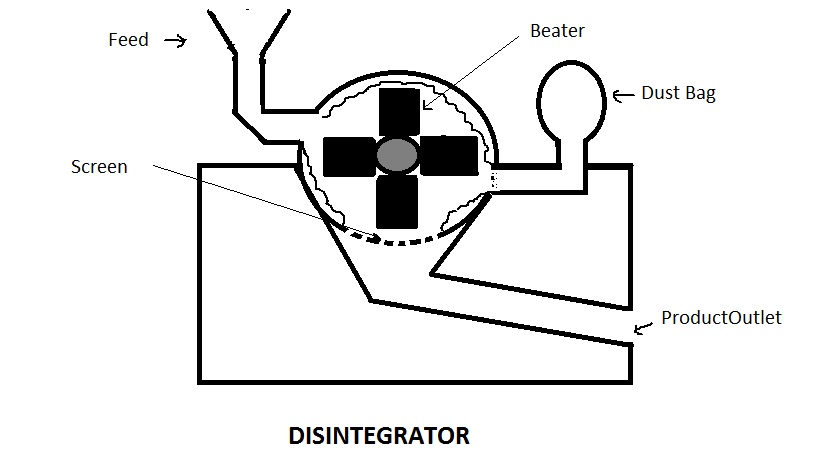
Size Reduction.

simplepharmanotes.blogspot.com
disintegrator reduction
Schematic Diagram Of The Froth Depth Measurement…. | Download

www.researchgate.net
froth schematic measurement
Schematic Diagram Of Pseudo-depth Domain Transformation Principle In

www.researchgate.net
Schematic Diagram Of The Experimental Setup. Depth A (− 10 Cm), Depth B

www.researchgate.net
Schematic Diagram Of The Disintegrator Beaters Pack: (a) Orientation Of

www.researchgate.net
Schematic Diagram Of Fertilisation Depth Measurement. | Download

www.researchgate.net
Schematic Diagram Of Depth Image Refinement Method | Download

www.researchgate.net
14. Technical Notes On Works Management. Part 3

chestofbooks.com
disintegrator diagram perplex fig works technical notes management part chemistry
Disintegrator System DSL-175; A) Disintegrator System DSL-175 In A Lab

www.researchgate.net
(a) Optical Schematic Diagram Of The Phase Depth Measurement System

www.researchgate.net
depth measurement optical
Schematic Diagram Of Depth Measurement. | Download Scientific Diagram

www.researchgate.net
Computing Process Of Device Depth Fig. 4 Schematic Diagram For Combined

www.researchgate.net
Schematic Diagram Of Instantaneous Cutting Depth | Download Scientific

www.researchgate.net
Schematic diagram of depth measurement.. Disintegrator reduction. Schematic illustration of the lcpc testing device (left side) and