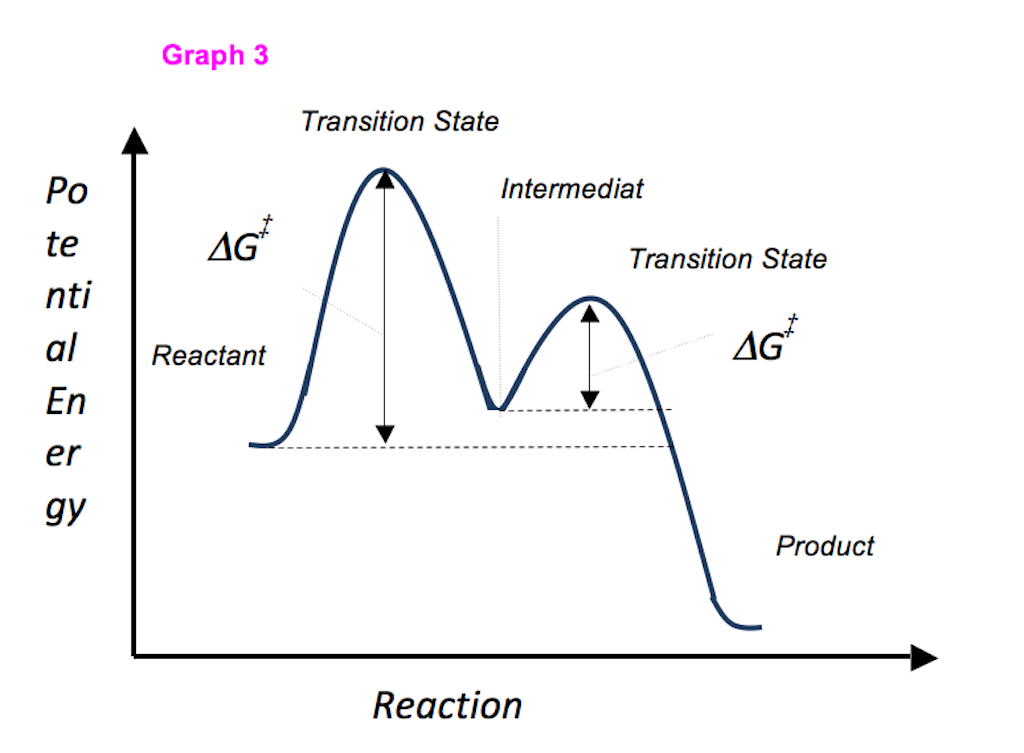
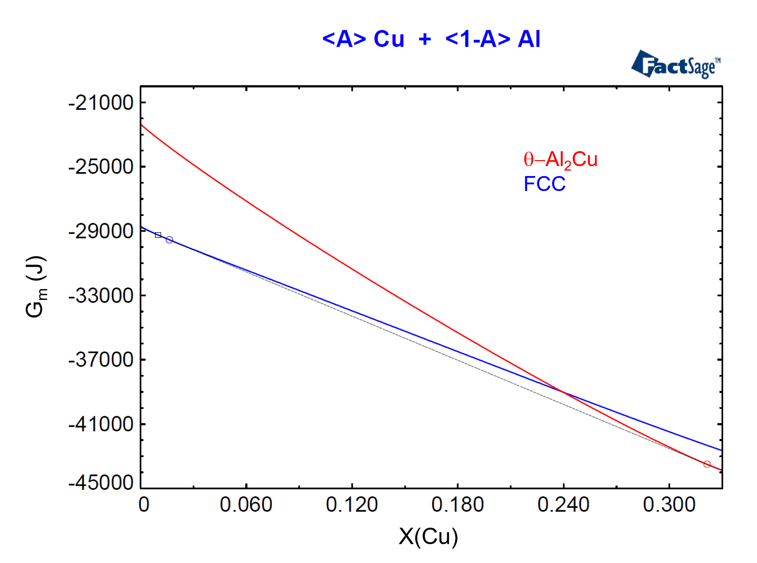
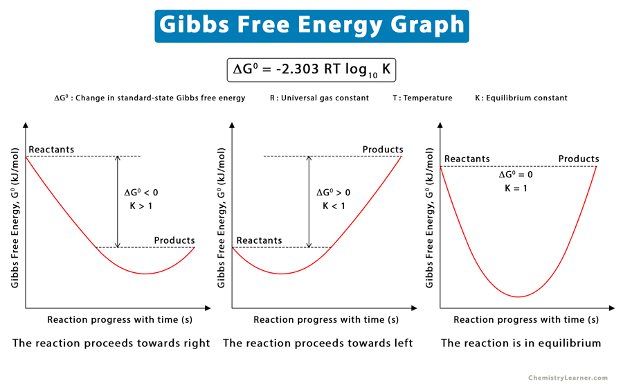
Schematic free-energy diagram for the phases involved in the MD is one of the most trending photographs on the web at this time. In addition to these photographs, Schematic illustration of (a) molar Gibbs free energy diagram for the, Schematic illustration of molar free energy vs. composition curves for and Schematic illustration of molar free energy vs. composition curves for additionally experienced a big enhance in search traits. If you are in search of viral pictures associated to Schematic free-energy diagram for the phases involved in the MD, on this web page now we have 35 pictures for you to discover. Right here you go:
Schematic Free-energy Diagram For The Phases Involved In The MD

www.researchgate.net
17: Schematic Gibbs Free Energy Curves For The Ni-Cr Binary At 500 °C

www.researchgate.net
The Molar Gibbs Free Energy Versus Pressure P At T = 2000 K. G—the

www.researchgate.net
Free-energy-composition Diagrams For (a) Ideal Solution, (b) And (c

www.researchgate.net
How To Read Energy Diagrams Chemistry

printablelibzeloso.z21.web.core.windows.net
Schematic Molar Gibbs Free Energy Vs. Composition Diagram Illustrating

www.researchgate.net
molar illustrating gibbs metastable
Molar Gibbs Energy Diagrams And Schematic Symplectite Geometries For

www.researchgate.net
(Color Online) Normalized Molar Gibbs Free Energy G = {G − G L (P E

www.researchgate.net
molar gibbs normalized
Molar Gibbs Energy Diagram Illustrating The Method To Calculate Onset

www.researchgate.net
From Molar Gibbs Energy Functions To Phase Diagrams – Part II – GTT

gtt-technologies.de
phase energy molar diagrams functions gibbs ii part technologies gtt figure
Schematic Illustration Of (a) Molar Gibbs Free Energy Diagram For The
www.researchgate.net
Energy Transition Zone At Britt White Blog

cedutuep.blob.core.windows.net
A Phase Diagram For Alkali Feldspar Showing Strain-free Solvus Vs

www.researchgate.net
alkali feldspar
Molar Gibbs Free Energy Diagram (G Vs X) Showing The Various Terms In

www.researchgate.net
Misfit Stabilized Embedded Nanoparticles In Metallic Alloys – Physical

pubs.rsc.org
alloys coherent precipitation rsc zones nanoparticles misfit stabilized
Schematic Molar Gibbs Free Energy Vs. Composition Diagram Illustrating

www.researchgate.net
gibbs composition molar illustrating metastable equilibrium austenite ferrite
Figure4 Relationship Between Farmland Soil [partial Molar Free Energy

www.researchgate.net
A Schematic Plot Of The Molar Free Energy As A Function Of Molar Volume

www.researchgate.net
A Schematic Plot Of The Molar Free Energy As A Function Of Molar Volume

www.researchgate.net
Schematic Illustration Of Molar Free Energy Vs. Composition Curves For

www.researchgate.net
General Reaction Coordinate Diagram Comparing The Free Energy Of An
www.researchgate.net
Standard Molar Gibbs Free Energies Of Solvation For (a) N-alkanes, And

www.researchgate.net
Molar Gibbs Energy Diagrams And Schematic Symplectite Geometries For

www.researchgate.net
Alkali Feldspar Solvus Calulated From The Analbite-sanidine Model (a

www.researchgate.net
What Is K In Gibbs Free Energy

mavink.com
Thermodynamic Calculations For The BCC Fe-Mn Bulk System. A Chemical

www.researchgate.net
Schematic Molar Gibbs Energy–composition (G–X) Diagram For A

www.researchgate.net
Schematic Graph Of The Free Energy Vs Mole Fraction Of Solute For

www.researchgate.net
mole fraction solute equilibrium concentration
Schematic Illustration Of Molar Free Energy Vs. Composition Curves For

www.researchgate.net
molar composition curves alloy
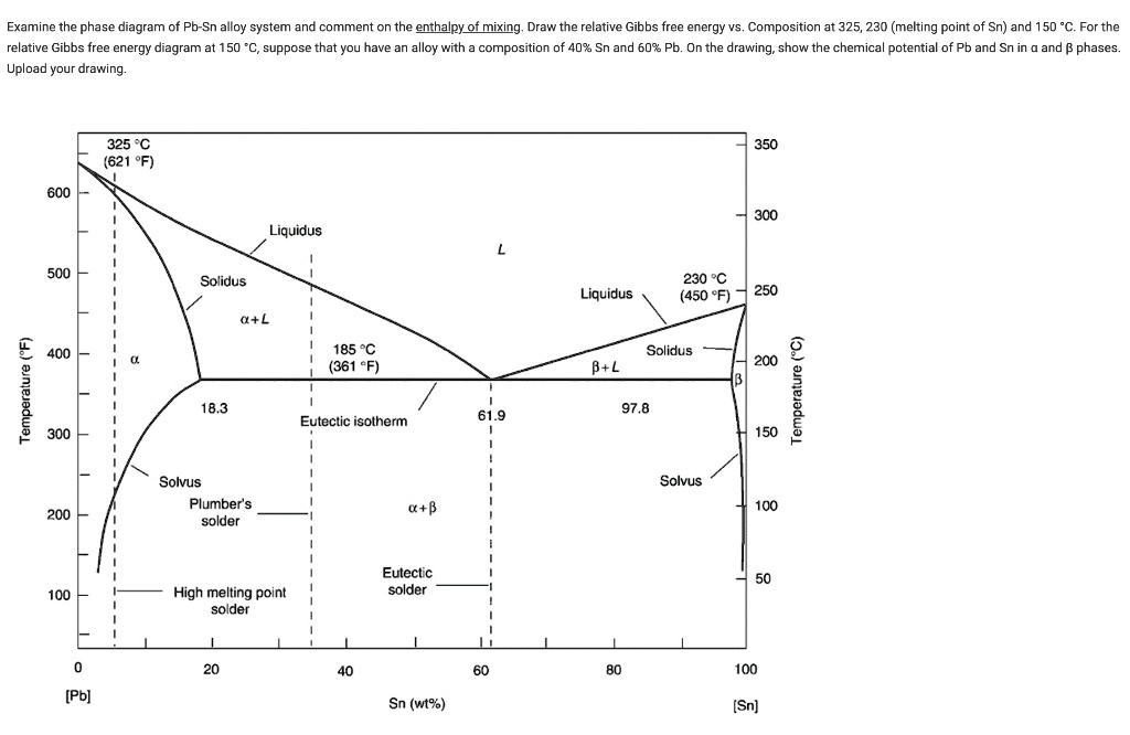
SOLVED: Examine The Phase Diagram Of Pb-Sn Alloy System And Comment On

www.numerade.com
Molar gibbs energy diagrams and schematic symplectite geometries for. Misfit stabilized embedded nanoparticles in metallic alloys. How to read energy diagrams chemistry